The Birth of a D-U87
MIc
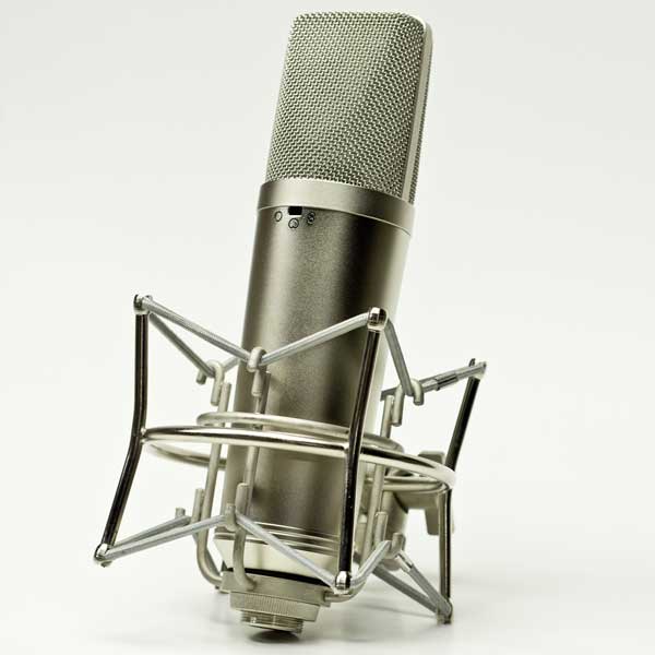
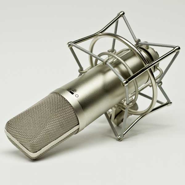
STY-5 mic body from studio939.com

Hi I'm Daniel Noga. I'm a professional audio engineer based out of Nashville, TN. A couple of years ago, I decided to learn about electronics. I wanted to learn what was inside these “magical devices” I used on a daily basis to record and mix projects, hoping I’d become a better engineer in the process.

I decided to build a GSSL which, I think, everyone in the DIY community is familiar with... After completing it, it works great, I still use it, and I learned a lot in the process... mission accomplished! Then, about a year ago, Dan Rudin mentioned these U-87 clones existed... After doing some initial research on the D-U87 groupdiy forum, I was sold, but never quite got around to it until...

I stumbled across some information saying the newer 2nd gen. STY-5 mic bodies from studio939 were in stock... sweet! Time to learn about these “magical devices” again... this time in the form of a microphone.

Dan Rudin decided he was “in” and graciously “sponsored” the endeavor. He’s building an orchestra room, is gonna need a few more microphones, and saw this as a great chance to see if a small army of clones might be the solution, so he commissioned me to build four mics.

There’s a ton of well documented information on how to build these D-U87’s, so rather than repeating what’s been done before, I’ve decided to document my personal experience with this build... trying to connect some dots and document what I discovered along the way.

By the way, Ferlyn Reyes was instrumental in this build. Not only did he take the pics for this qrite up, he worked in the background beside me every step of the way... and I couldn’t have finished these mics without him... thanks Ferlyn!
Step 1: The Beginning

I’ve used U87’s, knew there were different versions, knew I liked certain ones for certain things, but that’s the extent of my knowledge... so I figured the best place to start was to read, read, read. Here’s what I read to before ordering any parts:

Some of the things I learned in reading were:

    • This build is a clone of the older U-87I circuit, which means it has about 10db less output than the U-87AI.
    • There’s a FET in the circuit that needs to be biased... makes sense.
    • If you want a multi-pattern mic, you need a K-87 capsule (isolated backplates) for this circuit. Note: Newer Neumann U87’s use the K-67 capsule (shared backplate).
    • There’s a new pcb option from Dany at vintagemicrophonepcbkit.com
    • There are a lot of amazing, dedicated people out there willing to help people learn how to build microphones.

Step 2: Choosing/Ordering components

Ok, after reading, I had to make some decisions about parts. Here are my choices of components and a brief description of the thinking process:

capsule

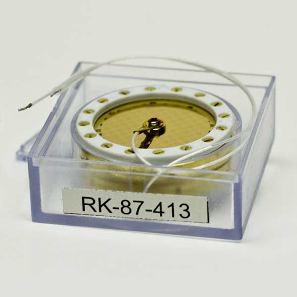
Capsule: I came across several options... everything from cheap Chinese imports, to hand crafted ones made in the ol’ USA. All of these options were found reading the groupDIY build thread. I decided to go with Matt’s RK-87 capsule from microphoneparts.com. Note: it has a thinner membrane than the original (3mm vs 6mm). This is not bad, just different... and from what I hear, back in the day, guys were modding their Neumann U87’s with 3mm capsules for a “snappier” sound. I decided on this capsule due to it’s price, quality (based on forum reviews), awesome documentation, and how awesome Matt is.

mic

Mic Body: There are various Chinese mics you can use as donor bodies. I decided to go with the studio 939‘s STY-5 body “3 pin + switch kit pcb ”. This body specifically works with the PCB I ordered. Plus, there’s no donor mic to gut, the body doesn’t have any logos/markings, it stylistically resembles the Neumann U-87, and the “in-stock” availability of studio 939‘s body started this whole mess!

transformer

Transformer: I decided to go with the AMI T-13 from tab-funkenwerk. Pricer than the cinemag option, but based on what I read, felt it was worth the price difference. Plus I learned about the passing of Oliver Archut (founder of Tab-Funkenwerk) and felt using the T-13 would help contribute to his memory. The T-13 is offered on sudio939’s site (save on shipping charges), but was out of stock, so I ordered directly through tab-funkenwerk... The transformers aren’t available to order through their web store, so I had to email them to order. Communication was great and the process was super easy. They just sent me a paypal payment request.

pcb

PCB: The obvious place to order the pcb is from Dany at vintagemicrophonepcbkit.com. There are three pcb options. The 2 older options using 2 smaller boards, and the newer, single board "Type M" design which is what I used. The single board design adds a little more $ to the build since you need 7 turret pins, but seems to be more convenient because it’s 1 board, and you can mount the transformer to it. Plus the newer pcb is blue, and we all know blue pcb’s sound better.

* Note: After this build, Dany has released a newer “new pcb”... I believe the pcb’s I used are no longer available. Please refer to the image to see the exact pcb I used.

caps

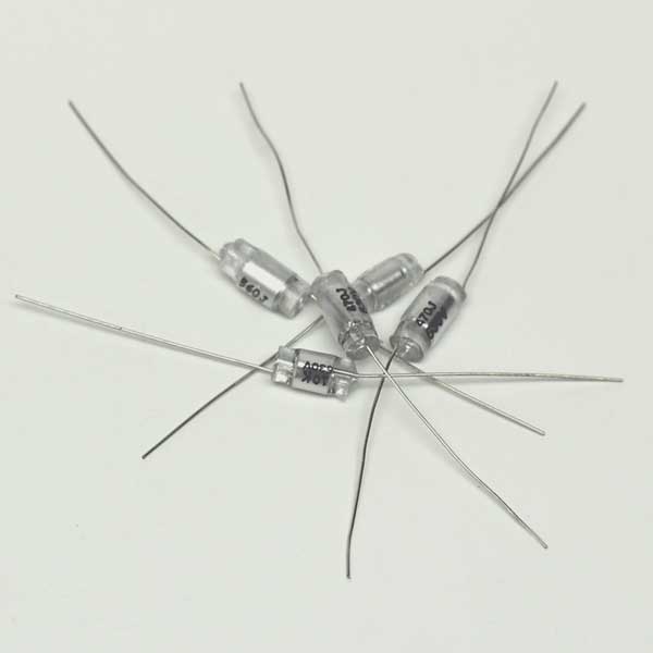
Capacitors (C1, C3, C4, C6, C15): This took me a bit to figure out. There seem to be two lines of thought. Your choice of what’s included in the official BOM (combination of electrolytic, film, etc), or you can go with Polystyrene caps, traditionally ordered through justradios.com. I chose to go with the Polystyrene caps for two reasons. The Polystyrenes are the original types used in the Neumann U-87, and people had recommended using the Polystyrenes when using the microphoneparts.com K-87. I was able to order the “Polystyrene kit” (shown in pic) when ordering the pcb’s from vintagemicrophonepcbkit.com. Saved me a little bit of effort versus ordering from justradios.com separately.

Other components: This also took me a bit to figure out. I used the BOM (Bill of Materials) from vintagemicrophonepcbkit.com as a starting point. I’m assuming it’s the same one as in groupdiy build thread. It’s pretty fancy... you click on it and it takes you to mouser.com with everything in your cart. The BOM included more stuff than needed for my particular build... caps if I decided against using the Polystyrenes, duplicate resistors (in case the originals were out of stock)... things like that. After careful comparison to the parts list spreadsheet downloaded from the groupdiy thread, I removed everything I didn’t need, added more of the things I needed, and placed my order. Here’s a link to my specific BOM:

* Note: Mouser was out of the WIMA film cap 100V .033pf (mouser # 505-MKP20.033/100/5) I found some other 100V .033pf caps we had lying around on the tech bench... wasn’t gonna let a litle ol’ cap slow down my builld!

Hook Up Wire: I got on ebay and searched for high quality 22awg silver stranded teflon wire... I think the stuff I ordered is “military spec” (oooooh... ahhhhhh). Ordered 5 feet of several different colors... that’s about it.

Step 3: Parts arrived!

The hardest part of the build was waiting for everything to arrive. I didn’t order everything at the same time so it took about two weeks from first order to last arrival.

I had a couple of capsules arrive with what appeared to be imperfections. I notified microphoneparts.com via email with some pics and they promptly replied saying every now and then a shaving can fall out of a bore hole in shipping... getting trapped between the membrane and body of the mic. They sent replacement capsules out, I sent the ones in question back and everything was perfect. Great service, great capsules, and great communication... I’ll have absolutely no problem ordering more capsules in the future.

shockmount

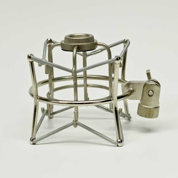
When I received the mic bodies, I had to immediately open the box and check ‘em out. The mic bodies are really nice... bigger than a Neumann U87 and heavier than expected. The shockmounts... not as nice as the bodies. Some of the plating was inconsistent... Maybe I just got the “special” ones. I didn’t feel it necessary to contact studio939... I know Chunger had to “pick his battles” with his supplier... but I was a little let down, mainly because the mic bodies are so nice, I had the expectation the shock mounts would be too.

The only other thing I noticed is that I’d have to order some screws to mount the main pcb to the mic body... M2 screws to be exact... Screws are included to mount the switch pcb in the switch pcb kit, so yo only need screws to mount the main pcb... a quick search on ebay took care of that.

Everything else arrived as expected.

Step 4: Stuffing

stuffing

I matched my L1 and L2 resistors.

Measured FET idss. They ranged from 6.25 to 14 idss. I set aside four FETs measuring 6.25, 7.4, 8.0, and 9.8.

I downloaded the “Build Pictorial” from the official D-87M build thread and stuffed accordingly. I wasn’t quite sure about the “tails” left on some of the components in the pics, but I figured it was easy enough to trim off later on if needed.

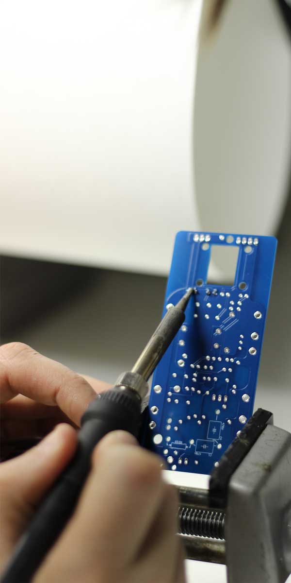
The stuffing was pretty straight forward... I only stuffed a few components at a time and went pretty slow to avoid stupid mistakes... I rather go slow, then have to troubleshoot later.

I didn’t realize the boards had the holes plated all the way through the pcb, so I wasn’t prepared for how fast solder would wick through to the other side... no worries a little solder wick cleaned that right up.

I intentionally left the variable resistor lifted off the pcb... so the ends of the legs were flush with the underside of the pcb... thinking it would be easier to remove later on... this turned out to be true.

Of course, I left the transformer off the PCB at this point... you have to bias the FET without the transformer attached.

Step 5: FET Biasing

I, or should I say “we” used the scope method. At this point Dan Rudin jumped in to help which made this rather ambiguous part of the build easy. I basically watched him do it and played more of a “supportive role”. He’s really the expert in all of this and I’ve learned so much from him over the years!

We soldered an xlr cable to the pcb, to provided phantom power from an api 512c in a lunchbox. Dan made the appropriate connections to his audio tools for tone, and then connected the scope. After a little of back and forth with tone levels, scope resolution, and adjusting the variable resistor, the FETs were biased.

We pretty much followed the method Matador described so well in the official group diy thread (you may need to scroll down a little to find his post):

Step 6: Switch PCB

switchpcb

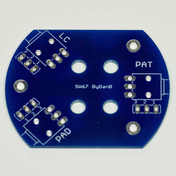
Pretty straight forward... soldered in the switches... Then I made sure the position of the toggle matched the markings on the mic body (which direction was on or off)... beeped out which switch pcb contacts to use, and attached wire, leaving the unterminated end to be connected the PCB later.

*Note: Make sure the switches stay flat/flush with the pcb when wiring. After finishing the first pcb, I noticed one switch wasn’t and was a pain to correct.

Step 7: Capsule Mounting

It was pretty straight forward once reading the directions here:

We ended up using the mount and stand that came with STY-5 mic bodies (versus what came with the capsules). It was already attached, and positioned the capsule a little higher in the head basket.

Just a few other notes:

    • As mentioned everwhere... DON’T TOUCH THE CAPSULE MEMBRANE
    • Make sure the backplate wires don’t short the backplates when attaching to the capsule... the screw rings are pretty close to each other.
    • Don’t forget to clean the construction crud off/out of the head basket and the capsule mounting post, etc. before mounting the capsule... it’ll keep your capsule happy.

Step 8: Final Assembly

I pilfered some multipair mogami for the xlr connection... unmounted the xlr connector, soldered to the xlr pins, mounted back into the xlr into mic body and kept it disconnected from the pcb.

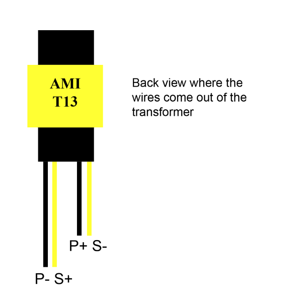
Next was the transformer. I was a little confused after reading about a batch where the wires were mislabeled on the transformer’s spec sheet, and there seemed to be conflicting info in the web about how to wire in... Dan Rudin to the rescue. He whipped out the multimeter and figured it out... primary vs secondary... which side to what solder pad.

This is how we wired it:

transformerdiag

Stripping back the transformer wires was tedious as I didn’t have wire strippers that small. I ended up using an exacto knife to “peel away” the insulation. I practiced this before cutting the wire to length and “doing it for real”, which paid off.

After the transformer was soldered in, I connected the xlr to the pcb. I screwed in the switch pcb.

The rest was connected to the pcb as follows:

Low Cut: Didn’t matter which wires went where. I pushed them through the back of the pcb and soldered in.

Pad: Didn’t matter which wires went where.

Pickup Pattern Switch Wires: This got a little confusing. The markings didn't match the circuit diagram (Neumann U87) I was referencing. I wired as labelled, after checking the mic out, turns out the F8 and the Omn were labelled reversed... and later confirmed by this information being added to the D-U87M build thread.

Capsule Wires: For some reason I didn’t order the turret pin for the hole labelled FBK on the pcb. No worries... I just crammed enough solder in the hole, inserted the wire and all was well.

*Note: Because of the use of the turret pins, you can connect the various wires on different sides of the pcb. I made my choices based on accessibility and what I thought looked “cleanest”.

Another thing that may be helpful is defining what wires get soldered to which symbols on the pcb:

    • LC: Low cut wires connected to the low cut switch.
    • PAD: One of the pad switch wires. The other wire is soldered on to the Bias In/FD turret.
    • FD: Front capsule diaphragm connection.
    • FBK: Front capsule backplate connection.
    • RD: Rear capsule diaphragm connection.
    • RBK: Rear capsule backplate connection.
    • CRD: Cardioid switch wire.
    • F8: Figure 8 switch wire.
    • Omni-FBK: Omni switch wire.

Step 9: Testing...1...2...3

Plugged the mic in and voila! I immediately had signal... but as mentioned above, my F8 and Omni was reversed. Back down to the bench for a quick wire swap and voila again! This time, with the the pickup patterns properly corresponding to the switch labeling.

As noted before, I was actually building 4 mics. I finished two first, and they were immediately put into real world testing... Dan Rudin had a string session the next day. We used them on an electric guitar cab, and even used one for a vocal session... sounded good!

I finished mic # 3 and uh oh, it didn’t sound right compared to the others. Almost like there was some phase issue. I triple checked wiring, swapped capsules, etc. No change. I wondered if the FET biasing went awry... Anyway, I set it aside and worked on mic # 4 which ended up not sounding right either. Ugh I was only 2 for 2. Dan Rudin came to the rescue again... after Dan poked around, he ultimately checked the biasing and sure enough, it was off for both mics. After re-adjusting the bias, both mics sounded great.

Step 10: Fixed resistor install... shorten hookup wires

Pretty self explanatory. Desoldered the variable resistor, measured its resistance out of circuit, and started the fixed resistor hunt. I ended up soldering a couple of resistors in series to get the exact number. One mic actually has three resistors in series and works great.

I went back and forth on whether to shorten the hook up wiring. I intentionally left them a little long to make it easier to troubleshoot. My perfectionistic ways got the best of me and I decided to shorten ‘em to make it as neat as possible... This ended up taking longer, and being a bigger pain than it was worth, so after shortening the wire for one mic, I decided to let the others be for now.

Step 11: The Shootout

What good is any write up without a shootout. Dan Rudin and I were able to borrow an earlier Neumann U87 AI from Mr. Richard Dodd. Despite the obvious differences we knew we’d hear, we used it anyway... Here are 320kbps mp3 examples. Try to guess what's what:

*The audio files are randomized for objectivity. The key is below each set of sounds.


Guitar 1

A

B

C


Gutar 1 Key


Guitar 2

A

B

C


Gutar 2 Key


Drums (Mono)

A

B

C


Drums Key


Piano (Mono)

A

B

C


Piano Key

This is how I ended up hearing things: the 2 clones sound pretty close to each other, and Richard’s Neumann U87 AI sounds totally different. All the mics sounded great in their own way... which mic I think is "best" would change depending on situation/application, room, musician, instrument, etc.

It's worth noting: The other 2 clones built (but not included in the shootout) ended up sounding awesome, but pretty different from any of the others... We weren't tring to make matched pairs so that's OK. From what I've heard, the classic Neumann U87's with this circuit sound different from each other too.

Step 12: To Sum Up

This was an amazing learning experience. I learned so much about U87’s. The most challenging part for me was having the patience to wait for parts to arrive and troubleshooting clones 3 and 4. If I had to do it all over again, I would in a heartbeat. Many thanks to the Dan Rudin, Ferlyn Reyes, and the DIY community for their dedication and hard work to helping others like me learn about the tools I’m fortunate enough to use on a daily basis.

About Me


My Name is Daniel Noga. I'm a Nashville based audio engineer with over 12 years of professional experience. I specialize in engineering, sound design, audio production and I'm the staff engineer for iV audio branding working with some of the biggest brands and advertising agencies in the world. When I'm not "on the clock" for iV, I work with a variety of talented artists, producers, and directors helping them achieve their creative visions.